Enterprise Network Architecture
Overall Network Topology
Frame Relay WAN
Full Mesh, OSPF Area 0
HQ <=> BR1
HQ <=> BR2
BR1 <=> BR2
HQ-Router
City A
BR1-Router
City B
BR2-Router
City C
HQ LAN
BR1 LAN
BR2 LAN
Detailed Branch Schemas
1. Headquarters (HQ)
HQ-Router
Gateway, Central CME & DHCP Server
HQ-L3-SW1
L2 Core, STP Root
HQ-L2-SW1
Access Layer
HQ-L2-SW2
Access Layer
2. Branch 1 (BR1)
BR1-Router
Gateway, Voice Gateway & DHCP Server
BR1-L3-SW1
L2 Core, STP Root
BR1-L2-SW1
Access Layer
BR1-L2-SW2
Access Layer
3. Branch 2 (BR2)
BR2-Router
Gateway, Voice Gateway & DHCP Server
BR2-L3-SW1
L2 Core, STP Root
BR2-L2-SW1
Access Layer
BR2-L2-SW2
Access Layer
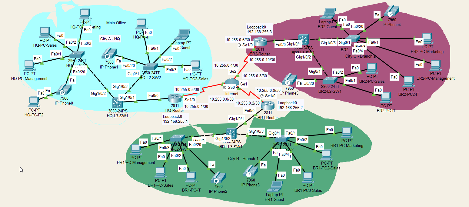
Full Network Topology
Detailed network diagram including end devices and port connections.
WAN & Frame Relay
-
Full-Mesh Architecture: The network utilizes a full-mesh Frame Relay topology. This allows any site to communicate directly with any other site, reducing latency and avoiding a single point of failure at the HQ.
-
Quality of Service (QoS): The
WAN-QoS-Policyis applied outbound on all serial interfaces to manage congestion and prioritize critical traffic like voice and call signaling over bulk data.
DLCI Mapping
| Connection | Router 1 | DLCI 1 | Router 2 | DLCI 2 |
|---|---|---|---|---|
| HQ <-> BR1 | HQ-Router (S1/0.102) | 102 | BR1-Router (S1/0.201) | 201 |
| HQ <-> BR2 | HQ-Router (S1/0.103) | 103 | BR2-Router (S1/0.301) | 301 |
| BR1 <-> BR2 | BR1-Router (S1/0.203) | 203 | BR2-Router (S1/0.302) | 302 |
WAN IP Addressing
| Network | HQ-Router IP | BR1-Router IP | BR2-Router IP |
|---|---|---|---|
10.255.0.0/30 | 10.255.0.1 | 10.255.0.2 | - |
10.255.0.4/30 | 10.255.0.5 | - | 10.255.0.6 |
10.255.0.8/30 | - | 10.255.0.9 | 10.255.0.10 |
Telephony Architecture (VoIP)
-
Centralized Call Management: The entire VoIP system is managed by a Cisco CallManager Express (CME) service running on the
HQ-Router. This centralizes control, numbering plans, and phone configurations. -
Branch Role - Voice Gateways: Routers at
BR1andBR2act as gateways. They use dial-peers to route all call traffic to the central CME at HQ for processing, rather than handling calls locally. -
Automated Phone Provisioning: Phones automatically receive their configuration. Local DHCP servers provide
option 150, which points them to the TFTP server onHQ-Router(192.168.255.1) to download their settings.
Numbering Plan
| Number Range | Assigned Site | Purpose |
|---|---|---|
1xxx | Headquarters (HQ) | HQ Staff Phones |
2xxx | Branch 1 (BR1) | Branch 1 Staff Phones |
3xxx | Branch 2 (BR2) | Branch 2 Staff Phones |
Registered Phones (ephones)
| MAC Address | Assigned Number | Site |
|---|---|---|
00D0.BA21.6903 | 1001 | HQ |
00E0.A385.973C | 1002 | HQ |
0090.2B3D.E76A | 2001 | Branch 1 |
0060.5C84.57C2 | 2002 | Branch 1 |
00D0.FF21.D0CB | 3001 | Branch 2 |
0001.6329.7EE2 | 3002 | Branch 2 |
Hardware Inventory
| Device Type | Model | Quantity | Role / Key Functions | Location(s) |
|---|---|---|---|---|
| Router | Cisco 2811 ISR |
3 | WAN Gateway, Inter-VLAN Routing, DHCP, QoS, Security (ACLs). HQ-Router also serves as the central CME. | HQ, BR1, BR2 |
| Layer 3 Switch | Cisco Catalyst 3650-24PS |
3 | LAN Core / Distribution Switch, provides trunk connectivity to access layer switches, STP Root Bridge for the local site. | HQ, BR1, BR2 |
| Layer 2 Switch | Cisco Catalyst 2960-24TT |
6 | Access Layer connectivity for end devices, enforces Port Security, provides PoE for phones. | HQ, BR1, BR2 |
| IP Phone | Cisco 7960 |
6 | Voice communication endpoint for users. Registers with the central CME server at HQ. | HQ, BR1, BR2 |
| End Devices | PC / Laptop |
16 | User workstations providing access to network resources. | HQ, BR1, BR2 |
VLAN and IP Addressing Plan
| VLAN ID | Name | Purpose | HQ Network | BR1 Network | BR2 Network | Default Gateway |
|---|---|---|---|---|---|---|
| 10 | Management | Device Management | 10.0.10.0/24 | 10.1.10.0/24 | 10.2.10.0/24 | 10.x.10.1 |
| 20 | Sales | Sales Department | 10.0.20.0/24 | 10.1.20.0/24 | 10.2.20.0/24 | 10.x.20.1 |
| 30 | Marketing | Marketing Department | 10.0.30.0/24 | 10.1.30.0/24 | 10.2.30.0/24 | 10.x.30.1 |
| 40 | IT | IT Department | 10.0.40.0/24 | 10.1.40.0/24 | 10.2.40.0/24 | 10.x.40.1 |
| 50 | Guest | Guest Network | 10.0.50.0/24 | 10.1.50.0/24 | 10.2.50.0/24 | 10.x.50.1 |
| 60 | VoIP | IP Telephony | 10.0.60.0/24 | 10.1.60.0/24 | 10.2.60.0/24 | 10.x.60.1 |
| 999 | NATIVE_VLAN | Untagged Trunk Traffic | - | - | - | - |
Key Protocols & Services
-
Strict VLAN Segmentation: A robust security policy is enforced via ACLs. Traffic is strictly segmented: communication is only permitted between the same VLAN across different sites. All other traffic, including inter-VLAN, is denied.
-
Dynamic Routing: OSPF (Area 0) provides robust and scalable routing between all sites, automatically adapting to network changes.
-
Advanced QoS: A detailed QoS policy on WAN links guarantees 30% of bandwidth for Voice, 10% for Call Signaling, and the remaining 60% for Data, ensuring pristine call quality.
-
Distributed DHCP: Each router (HQ, BR1, BR2) provides DHCP services for its respective local VLANs, ensuring high availability and keeping address allocation traffic local.
-
Access Layer Security: All access ports are hardened with Port Security (restricting MAC addresses), PortFast (for fast convergence), and BPDU Guard (to prevent switching loops).
-
Management Security: Remote device administration is secured using SSHv2. Access is restricted by an ACL, permitting connections only from the secure Management VLAN (10.x.10.0/24).